

source: https://vimeo.com/375782717?embedded=true&source=vimeo_logo&owner=1723479

- Switch interface from Build to Solaris
- under obj network build a geometry and inside get a sphere primitive > change to mesh

- in viewport select the top roll of poly
- either hit tap in the viewport to add a group node

- or in the group node properties hit the arrow to select the top roll of polygons. after select, hit enter to confirm the selection
- give the group name as top

- for the bottom roll, use a group combine node
- set the name of this group combine > specified it as Equals all but “top”(the group name)

- end the geo with a null > rename the null to OUT

- switch network to stage(don’t need to get lopnetwork in stage) or bring in a lopnetwork node inside obj network

- continue with obj network but highly recommend to switch to stage network for solaris
- get a lop network node
- inside the lopnetwork > get SOP import to import the sphere and other object. Can also get USD import

- in sop import click on the arrow to open floating operator chooser then choose the sphere OUT from the list
- scroll down for subset group. type in the both group name. because there has 2 groups. so the import group section won’t pick both of them. It needs to use subset group instead.
- in the scene graph tree now it’ll show the sphere mesh primitive and its geometry subset.

- for this demo, add a few more object geometries in the obj network
- add those into the lopnetwork by using SOP import. and again they can be USD import from production


- transform them little bit off the ground if needed
- add a SOP create grid for the ground and rename it
- put a merge node to merged them all

- add the material library node


- get 5 principle shader inside material library for this demo
- name them and set them all with different colour.

- in the attribute of the material library node > hit auto – fill materials
- The materials should be shown into the scene graph

- add a assign material node


- drag and drop the geo and the material from the scene graph to the assign material slots
- hit + to add more material assign slots


- add a light, change the light type if needed
- move it to a desire location

- add a dome light > change its colour
- merge the lights with the assignmaterial node


- add the Karma renderer node after
- and now the viewport should be able to switch to karma view

- in the Karma node attribute, switch it to XPU for a faster render result

- for a floating renderview, go to window > new floating panel
- switch the panel to scene view

- change the floating panel network to obj/lopnet or stage/lopnet depends on where the lopnet graph sits at
- and then the view can be set to karma

- back to the graph
- add another light to the merge. change its light color.
- switch the light to disk
BigPS: better scene graph hierarchy. By default SOPimport note will not put the imported geo inside a group. It is a good practice to put the imported geo inside the geo group like in katana.


- For all of the SOP import node. Put /geo/$0S in the import path prefix
light linking:

- add a light linking node before karma render node

- in the light linking node > right side the geometry > select the geo(s) and create a collection

- Drag the collection or just the light into the center rules column
- then drag the light to the rules colour to either link or unlink to perform light linking
Light Mixer:

- add a light mixer node after the light
- in the property of the mixer node. drag and drop the lights on from the list to the right side
- change to sliders view to adjust each light properties
- the star column is for solo mode

- red dot indicate it has been edited, right click to revert changes
Snap shots: not only store the render but the whole network. any value, even node structures are stored with the snap shot


- click on the little screen split bar to pop the snap shot section out
- click on snap to store

- right click and revert network to this snapshot will go back to that setting. not only limited to light mixer but everything to the stage network
render to disk


- inorder to render to disk, needs to add a camera
- in the karma render settings node > sure the output picture location by default $HIP is to wherever the scene has saved at
- set the camera, resolution, primary samples, min and max sample for the secondary
- under image output and filters > the denoiser options are for nVidia GPU only. It will works for both CPU and XPU render.

- under render > scheduler > show the progress of the render and jobs being line up


- the USDrender_rop node will have the render to disk button
- the location should create an extra render folder as the output picture suggests.
ps. if for whatever reason the camera go tilted:
- focus reset cam: space + g
Collection and Instancer:

- create a cube, sphere, torus in obj network

- SOPImport all 3 of them into lopnetwork in stage network
- add a SOP Create grid just to demonstrate stagemanager
- merge them together
- add an instancer

- inside instancer, need some sort of point for the object to put on. For now, put an add node in there so it has at least 1 point to work with
- click on preview on the add node and get back out

- in the instancer switch prototype index as Index for preview
- drag the index number to see each object
Stage manager: put geo into groups


- connect the stage manager after the merge
- for the option. hit the plus to add a folder
- name the folder and put some the objects into the folder
To utilize it, need to convert this folder into collection
Collection:


- add a collection node after stagemanager
- in the collection option > set a collection name
- inside primitive type in the /folder name/ with / / inbetween > put star at the end to grab all the geo inside the folder
- now the object inside the folder has become a collection and that collection can be use in instancer

- connect the instancer back
- set the prototype Primitive to %collection name
- now when drag the index number. It will only show the object which is with in the folder and the collection
Instancer(advance):


- now when the prototype index set to Random
- and inside the instancer get a grid or any other object that can draw more points the instancer will scatter the object from the collection

- further more to add a scatter node it’ll have futher control on how many object scatter across the object points.
Attribute Wrangle:


- set the prototype index to index attribute inorder to use the attribute wrangle
- go into the instancer node and add an attribute wrangle node at the end
- in the VEXpression type in: i@index = 1;
- so now this will show the index 1, if it change to 2 it’ll display only index 2. just like dragging the slider from the outside but now control by attribute expression. by that, it can map into a noise value

- add an attribute noise node before the attribute wrangle
- set the name to c and make it a float
- operation to add, and range value min 0 max 1

- in the attribute wrangle change the expression to: i@index = chramp (“i”, @c);
- click on the create parameter button at the right to create a ramp
- set the point on the left to value 0 and the right point value to 3 so base on the ramp it scatter across 0 – 3 value base on the noise

- it can to finer adjustment to put constant value to the ramp to fully control how much 1 and how much 2 and 3 are mapped across the ramp
- also add another VEX to control the scale: @pscale = chramp(“‘”ps”, @c);
- press create spare parameter button on the right

- further adjust the attribute noise element size and roughness

- for random orientation can use an attribute randomize
- set the attribute name as orient and dimentions to 4

- packed the instancer group with the output node at the end
Assign Material to poly groups for instancer: Experimental


- for each object>create group node> select the poly and put them into the group(previously covered)> give the group a name

- back to Stage / Lopnetwork /
- create material library , make a few materials for each type so in this case there ha 3 materials, cube_mtl, sphere_mtl and torus_mtl

- for assign material node > put that before the stagemanager and collection node
- drag and drop the mesh group for material assign and the material accordingly

- for the instancer > plug in both the primary and 2ndary input. for some reason the 2ndary input doesn’t carry over material library in scene graph. but for only the primary input then then the material assign needs to include th einstancer path. so pluggin into both the primary and 2ndary seems the only way(further investigation needed)

- at least is to add light / camera / karma for the render
Randomize basecolor attribute parameter:


- for this example will randomize basecolor of the materials
- into the instancer
- add an attribute randomize
- set the attribute name as basecolor

- get back outside of stage/lopnet/ instancer node
- point attribute to copy > add basecolor at the end
- make sure to use karma cpu to render. as of 19.5 xpu doesn’t support randomize basecolor attribute
Assign randomize material on instancer with attribute: (might not work, seems like bug)

- add attribute wrangle and assign a vector attribute with the value of 1, in this example for the cube type in: V@cubeVector_attribute = 1;

- back to stage / lopnetwork / all the SOP import node
- check on the attributes > add the existed attribute that has just been assign to the animal.

- inside the material library > add a bind node and plug into the basecolor
- the name of the bind node rename it to the custom vector attribute name

- inside the instancer > in the attribute randomize, put the custom attribute name cubeVector_attribute into the attribute name

- in the instancer node > point attribute to copy > also should be the custom attribute name cubeVector_attribute
USD export possibilities:
setup the geo with multiple groups and additional attribute

- make sure the geo is not primitive otherwise it will not import into lopnetwork correctly > in this exmaple of a primitive sphere, switch it to geo mesh

- setup multiple groups with unique given names

- use attribute create node to assign one of the group with an attribute name
- close it will the OUT null
- save the houdini file
lop network multiple variations of the sop import:

- in stage > lop network > sop import, load OUT_sphere from make sure it is load as reference
- noted that by default the path in the scene graph is set to /sopimport1
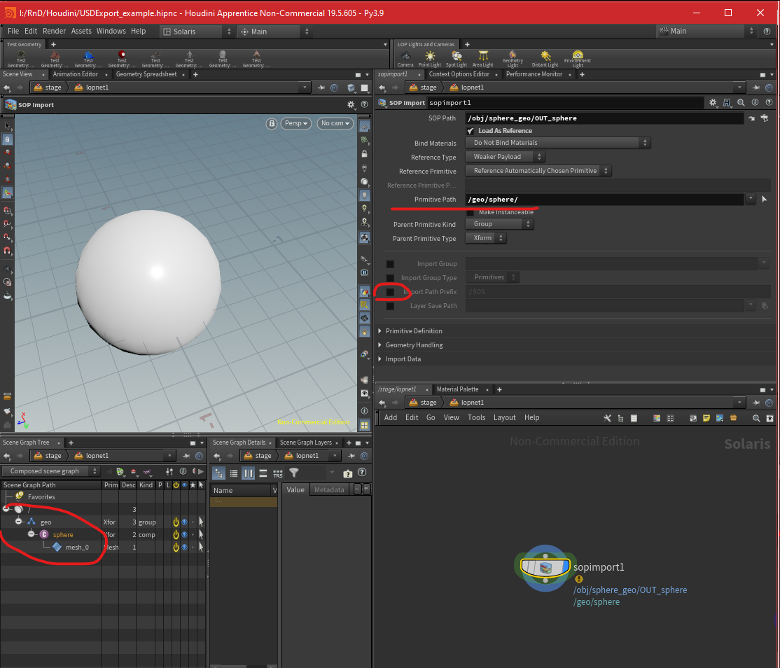
- change the primitive path to a desire hierarchy in this case /geo/sphere/
- noted from the scene graph that the geo is being put inside as such
- check off import path prefix

- check on the import group and assign the group names to bring in all the groups

- for the usd file layer save path save where the houdini file is and create a geo folder to put in this usd file

- assign the groups into subset group for material assign

- load the attribute that was being created

- name this sop import as the original
setup individual hierarchy of the groups as subcomponent

- duplicate the original sopimport by alt drag
- change to just load the specific group and the output name as the specific group as well
- connect them one into another so in scene graph it is in proper hierarchy. Just like loading 2 different object into scene graph

- however they are loaded in as “component” which is fine but it can be redefine them if needed

- get a configure primitive node
- put in the path of things that needs to be change in this case is everything after the sphere group so it will be /geo/sphere/*
- and change the kind to subcomponent
setup USD variant export

- get the add variants to existing primitive node
- close the previous chain with an out null
- connect the OUT null to the begin and end of the variant block
- add a null in between for the name of the variant

- add a prune for the branch out variant
- prune out the groups that don’t need

- also get a null for the name of the variant

- connect that to the end variant block
- set the primitive path the same as how it was being setup in the scene graph
- name the variant set to the name of this asset

- add a set variant node

- from the pull down of the varient set it should have the set that was just being assigned from the block
- after that the varient name should pop up the 2 names from the variant block null name, pick the one wants to be default when it load

- add a configure layer node

- pick the default primitive from the drop down
- then pick the save path from the drop down

- end with a USD Rop node to write out the file

- make sure “use relative paths” is enable
- set the output file name
- hit save to disk
- the primary one will be outside of the subfolder and the variants will be inside the subfolder
note: currently I have no idea why it write into usdnc file instead of just usd
USD UV Texture: texture loading node that can be use for Karma and materialX. However, Haven’t found supportive artical about the usage and benefit of this image node
feedback colour is the default colour when no file is loaded

MaterialX: open source material that can be supported and rendered in different engine. Also allow to store in USD. MaterialX has its standard surface uber shader that covers pretty much all attributes. However if user wants to create their own. Using subnet node to put desire attribute in it to create custom shader.


- inside material library, get a subnet node. It is recommended to rename it
- MaterialX has its own version of subnet that only allows materialX nodes inside the materialX Subnet

- The auto fill material in matterial library may not pick up any subnet that doesn’t have a unique name. However, they can always fill it in manually even if the subnet did not rename


- inside subnet there has the input and output node. More importantly is to make sure the custom node is output to the output node.
- The MaterialX subnet has slightly different nodes inside. As it has already prepared a displacement output

- also node that inside the materialX subnetwork. Output node usage can be changed eg: for volume shader, displacement sader, etc

- since subnet can build any type of custom shader including Karma shader. To utilize materialX shading network. Get materialX surface and materialX surface material node


- for a base material get a diffuse BSDF node.
- diffuse bsdf include diffuse colour and its roughness value
- as for materialX subnet, there has no need to put the materialX surface material in between


- to add specular reflection, the diffuse bsdf node needs to layer(verticle blend) with a dielectric node
- the dielectric bsdf node will have the attribute for ior, reflection, roughness, etc

- however for metallic material. A conductor bsdf is needed. It’ll have the ior and extinction coef attribute. As well as the normal for it


- to be more artist friendly, get the artistic ior node for calculating the correct ior and extinction coef value.

- to transition dieclectric and metallic material a materialX mix(horizontal) node is needed


- after the mix(horizontal blend) user can add an additional dielectric bsdf node with a layer node for an additional clear coat blend (verticle blend)
- additional node can be added as a verticle blend such as sheen and thin film


- back to the subnet node, it can add custom parameter by clicking the gear icon
- the parameter page will pop up. simply drag and drop the parameter that wants to be expose to the editor. Put the name(parameter name) and label(the display name for user)

- hitting apply will have the parameter exposed.
- using can always right click on the the parameter name in the editor to group/tab the parameter for further UI adjustment.
materialX image: this is the image node for materialX
- besure the signature type is fitting to the input. eg, for roughness the image signature should switch to float 1, normal as vector 3, etc

materialx normal map: is a normal map node just like every other render engine
- be sure that the input image node is set to vector 3. for a default normal value should be 0.5, 0.5, 1

- normal map will kinda blur off if subsurface is fully in use. It can balance it by reducing the subsurface gain or simply use displacement map.
Material Geometry Property Value: this is a PrimVar node. And it’s also available for UV coord. switch the signature to vector 2 and the Geomprop to uv then it’ll read the texture coord for the image node. Some render engines need this to map the texture properly.


- if the geo has some attribute being define in the obj network. those attribute can be recall by geompropvaue node.
- Select the mesh in scene graph. look into scene graph detail.
- Put any primVar value into the geompropvalue node geomproup input. define the signature type.
MaterialX absolute value: this node gives pure value. no need to assign a name and become an attribute or stick an extra value to the shader. it is purely a value node that can link into any shader for master control value. It can give out color/vector/float values.


mtlxTextureCoord and mtlxUSDTransform2d: these 2 combined to perform a 2d placement texture coord where user can rotate scale translate the UV. Instead of using geom property value. This setup will be more useful in most cases

Procedural 3D node and materialX position node: all the procedural 3d node like noise nodes require a position input. MaterialX Position node is like a 3Dplacement node in maya

- pick either model or object will make the texture translate with the model when it moves.

- add a multiply node to multiply its position value to have a tighter procedural noise
Export: it is better to include a material surface material node even on a standard surface uber shader for export. Simply right click on to any node and hit save as materialX. Other application like Maya/clarriss will be able to load it.

focus view: space + f
home view: space + g
Material library / Material network: material library inside stage is the same as material network in obj. but if user choose to put material network inside obj. Later will need to sop import that material network into stage or lopnetwork


- inside obj network, get a material network
- create some materials inside it
- go to stage network
- get a scene import(material node)
- by default the node is set to import everything in the additional materials
- or it can be manually enable or disable the list of material that wanted to be import by clicking the bundle chooser button on the right
VEX base normal map node : displacement texture

- get a displacement texture
- switch the texture type to normal for normal map
MaterialX Displacement: It is best to put materialX shader in a materialX subnet. MaterialX Subnet has a proper setup for displacement.


- make sure the image node output set to float
- houdini’s scale is 1unit =1meter. So the displacement scale should set to 0.01
- since the materialX displacement doesn’t have any default height option so a remap is needed
- depend on the displacement map is half float or full float. remap needs to be adjust accordingly. If it is a baked 32bit displacement map with negative value, then it shouldn’t need a remap node.
- some of the Megascan assets require to color offset their displacement map. To do that, use a color correct node to reduce the gain to 0.75 will have a better result
ps. houdini 20 for remap, set to colour4(FA) somehow remap float will be gone when a triplanar image node is pluged in
USD export: source from NINE-BETWEEN https://youtu.be/cE-Bbdspu_8?si=phqFLsGokzNE9o3

- assuming there has 2 variant of the asset inside the geometry node


- inside stage, get a component builder
- in the first component geometry node, change source to external SOP and pick which variant wants to be saved
- rename the component geo node of with _variant for practical reason

- in side the material library
- create a material
- rename it , make sure the material is flagged with the orange icon on the right


- since the material is renamed properly it’ll show its name at the scene graph
- component material is like the assign material node
- The material path of the component material node will put in the same name of the renamed material automatically with the default script
- the script will grab the first material that is sorted by alphabetical order.
- however since it component material node works like assign material node. it should be able to assign those manually
- make sure to rename the component material node


- at last rename the component output name as it’ll become the file name of the USD
- recommend to generate thumbnail by checking the “view thumbnail camera” button, set the viewport to Karma and hit generate thumbnail button
- hit save to disk and it’ll generate 5 files. the geo usd, material usd, an usd that reference the 2 , a container usd, and a png for thumbnail
Reference node: to load USD file

- simply select the file from disc on the file pattern input
export USD assets with multiple variants:


- duplicate or get tanother component geo node. select the desire obj output
- add a component geometry variant node. it is like a merge node

- add an extra material
- make sure to auto-fill the material

- for the component material node.
- instead of using the script for the material path. drag one of the material onto it. leave the primitive as the script so it applys that material for both objects
- make another component material node. drag the other material over to the material path so all objects will have the 2nd materials as well.
- path that into the graph. so now both 2 objects should have 2both material assigned to them.

- to export this USD file, make sure the component output node is no longer just the single asset variant name. choose a name that can represent all the variants
- save the file and it’ll create another folders that contains the new 4 USDs
explore variants node


- add the explorvariants node to check.
- set the mode to varaints
- set layout to stacked XY
- give a bit of spacing
- this can be used after the reference node to check the output USD file
Layout node: to reference USD and populate in a scene

- recommended to prepare assets using solaris layout asset gallery
- in the solaris layout, add a new layout asset gallery pane

- by default it’ll load the default houdini asset database
- create a new data base
- browse a location and save a .db file recommend to save with the usd export asset folder

- now it the gallery is empty.
- hit the bear+ icon to add asset
- load the usd file with the thumbnail that has generated during the usd export
- then the asset will be added to the gallery

- get a geo that wants to be scatter or plays the objects on. in this case there has a grid
- get the layout node
- in the layout node, drag and drop the asset from the gallery

- make sure the layout node is selected
- select the asset from the list
- pick a tool, in this case use Place to place it manually
- hit enter or the show handle button on the left
- start dragging on the plain to place the asset. hold and drag to adjust the size

- in the option by default the method is using Point Instancer. this is a more memory conservative way. because it doesn’t matter how many asset been placed it will consider as a single layout item

- however it can always be split into multiple individually by choosing instanceable reference then now it’ll split into multiple item under layout

- by RMB on it. user can choose variants
- it’ll automatically add a setvariant node into the scene

- or this action can be done manually by placing a set variant node
- drag and drop the item that wants to be switch variant
- select the varient set. either geo or material
- and choose the variant name or pick from the drop down menu
Instancer and collection with USD: source:NINE-Between example


- get an instancer, weather feeding a geo outside or the instancer or insider are fine
- if the geo is feeded outside, get a lopimport node inside the instancer


- pick a LOP path
- then pick the primitive within it.

- get an unpack USD, switch the output to polygons to define some attributes


- drop an attribute paint node to paint some mask by hitting the icon on the right and press enter or the geo select button at the left and start painting
- inside the attribute paint node, go to attribute, and give the attribute a name. by default it set to mask.


- get a scatter and align node
- adjust the coverage if needed
- or to utilize the mask by changing the point mount method to by coverage
- check on the density attribute and pick the mask or type in the name of a painted mask

- going back to the stage network
- add a reference node feed into the instancer
- pick the USD file at the file pattern.
- then it should scatter with the USD

- to randomize the variant, add an explore variant node
- leave the mode to duplicate variants

- add a collection node in between
- give a name to the collection

- drag and drop the path of a desire reference asset into the primitive
- add /* to the path at the end to indicate everything within the reference folder


- going back to the instancer node
- At prototype primitive > add or replace the collection from the drop down menu
- uncheck only copy specified prototype primitive
material library Visualize node: to preview a node or a chain

- select any node and press x for activating visualize node
Edit material network: the node that allows to reference edit materials for lighting

- add the edit material network node after reference
- drag and drop which material wants to edit in the material path
- hit load

- inside the edit material node there has 2 parts that split by the collect node
- top part for reference edit the shader
- bottom part is a basic preview shader in case the engine can’t read any of the shader
- everything is gray out, check the attribute that wants to be edit an edit it
- inside this edit material node, using can add or subtract nodes into the shader if needed

- there has an enviroment variable that can always viewport display the preview shader to save some resources. will google that later
Load simulation into solaris and export usd after lighting and scene assemble:
source from Nine between: https://www.youtube.com/watch?v=cE-Bbdspu_8&t=7382s
sublayer node: it is like a reference node but it can load multiple references and off load them when they are not needed.


- loading USDs with sublayer node in stage network
- lopimport it in obj network
- unpack the usd so it can be edit again
- convert it to vdb for collision
- convert it back to poly

- do the particle simulation thing
- most important is to set attributes


- make sure the simulation has P(position), pscale(scale), v(velosity)
- click the little trail icon on the side of the obj network viewport to view the velosity
- hit D for display option under geo, point size to view pscale
- pscale and v will take use in render. if they are not defined, it’ll default to a value of 1 which will make them super huge in render
- also make sure to delete the attributes that is not needed to reduce a USD size after

- back to stage network
- bring in the simulation with a sop import node
- make sure the import path prefix has /sim/$0S to put the simulation in a group
- add a material library and a light

- assign the whole sim group to the shader. either directly to material library or assign material node

- adding velocity motion blur in Karma render settings
- since the point primitive(the simulation particles) have velocity, under karma render settings > camera effect > swich velocity blur to velocity blur. then now it will take that attribute into use. There will be no effect if there has no v attribute. (may need to rename the v attribute to velosities)
- It is common to add multiple Karma render setting node for different resolutions of render for preview and final renders
USD Rop node: output the render information, the whole lopnetwork into USD so even by different render engine can render with this information.

- set a frame range, by default it renders only a single frame
- the output file name there has no need to add .$F. in the file name to output a file every frame. Unless it has too many frames or need to split into 2 renders.
- may also switch on “flush data after each frame” when splitting usd files for clearing caches.
MaterialX Volume shader:

- the velocity is set to the same as the density so velocity doesn’t exeed the density.
- make sure there has the density attribute because it’ll be needed for primVar later


- bring in the sim as it was from the previous section
- get a materialX subnet, since the subnet output default is a surface shading output, change it to volume

- add a materialX volume
- vdf: for smoke(density)
- edf: for fire(emission)
- note: if not using mtlxSubnet, than just start the shader with the mtlxvolume under material library

- assign to volume primitive to the material library or assign material node

- adding a materialX Anisotropic VDF node, increase the size. There should have voxel showing in the render. This is just to visualize the bounding of the voxel.

- something to note is that somehow Karma doesn’t refresh when rendering volume shader. Restart render if it doesn’t render anything

- get a materialX Geom Prop Value to recall the primVar: density attribute from the simulation
- connect it both into the anisotropic absoption and scattering. That will replace the value that was punch in earlier.

- by adding multply nodes to future control the density value

- note that the anisotropic is accepting vector 3 data, so that means it can bring in the colour
- multiplying the density with a constant colour
- bring an materialX constant, switch the output to colour and multiply it with the primVar multiplied value for both absoption and scattering
- the colour for absorption is a extinction base so it’ll render the opposite colour. scattering input is not.
Camera:

- be ware that the number in the close range clipping range and the focal length value my blown up. reset them if needed
- suggest to keep the close clipping range low otherwise stuff will get cut out


- depth of view control by F-stop and focus distance. F-stop 0 means no DoF
- with the transform handle and the camera selected, hit shift +F will show focal plain
- shift+click on anywhere again will focus on where being clicked.
AOV

- check on the pass if needed and it’ll show in the render output


- under the aov tab, there has a section for extra render vars
- hit the + and type in the name of the aov or select from a drop down on the right.
LPE tags: similar to light partitions that can store along with passes


- when the split per LPE tag is activated in the AOV, in side the light under karma tab
- under LPE tag, switch to set or create
- type if $OS(or custom name) to set the tag as the name of the light
- it’ll add another pass for the aov that has checked on split LPE.

- by default the denoiser is only added to aov C. click on the left to add denoiser to more aovs
USD Render Rop: a render node


- after render settings are done.
- set the render current frame or range of frames in the rop node. hit render to disk
- if multiple render settings node has added. under render settings drop down should have different renders settings to select. Make sure the other render setting primitive is set to a different name
- render delegate is to choose render engine
Configure Layer: is a layer node to output different path command for USD to split different catagories of the scene in to different USDs

- either by typing start new layer or configure layer will bring in the same node. start new layer will have some different default settings

- by default under the scene graph layer tab any object either generated by houdini or reference in will be set to implicit in save control

- bring in ta configure layer node and set its save path will turn the asset into explicit
- it is a good practice to separate the configure layer node with a null to make the graph more readable.

- Can give another configure layer to all the lights and another layer to all the cameras
- when they merge with a merge node, set the merge style to separate layers

- for asset that being scattered by layout and instances . The configure layer can be set to flatten layer so it combines the whole thing together.
- noted that the referenced in asset will not be saved.

- by the end for the USD Rop node, change the save style to flatten implicit layers
- then hit save to disk

- The ROP will save a container usd file that contains the location of other branches USDs
- Work with software engineer to setup a better database folder structure for pipeline.
Bring pivot and object bottom to ground level:

option 1: use match size node the from value> set justify Y to min > leave X Z to center

option 2: transform node set translate to -$CE to X and Z, Y set to -bbox(0,D_YMIN) to move the object to center above ground. Then pivot translate to the opposite direction as $CE X and Z , Y to bbox(0,DYMIN)
Show UV space: in sop (obj) > select geo > Space+5

